- For the protection of multi-load cell installations such as silos and tanks
- Reduces down-time via immediate alarm and fault diagnosis
- Provides an assured working system in critical applications
- Avoids material shortage, overflow or incorrect batching from damaged load cells or cables
- Now supports both 5V and 10V operation – 5V operation requires less power from the
connected instrument - The alarm will be activated if:
- One or more load cells are out of balance
- Any load cell is operated outside a preset mV/V range
- Excitation voltage deviates from preset range
- Any connection is lost (open circuit detection)
- Any short circuit is detected
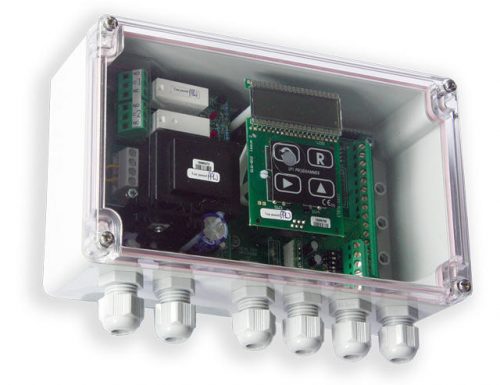
Load Cell Junction Box & Fault Monitoring Alarm (LCI)
$344.00
Description
The LCI load cell failure alarm is designed to continuously monitor the condition of individual load cells and activates an alarm when faults in the system are detected, therefore providing increased safety and cost savings onsite for all weighing systems.
The latest version of the LCI now supports both 5V and 10V operation, 5V operation requires less power consumption from the connected instrument and simplifies barrier selection.
It provides protection for multi-load cell installations such as silos, tanks and other systems where the failure of an individual load cell can have serious consequences such as material shortage, overflow, or incorrect production batching. The device constantly samples the individual load cell channels and activates an alarm if any failure conditions are detected, ensuring a safe working system.
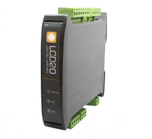
The LCI should be used in conjunction with a host intelligent weighing instrument such as Mantracourt’s ADW15, LCA20, LCD20, SMW etc. as well as suitable third-party products.
For a simple summing circuit with no trimming and no corner compensation, use the Load Cell Junction PCB, model JPP Load Cell Junction PCB, and for trimming and corner compensation, use the Active Junction Box, model JBA Load Cell Junction Box.
LCI
| Title | Version | Size | Date added | Download |
|---|---|---|---|---|
| LCI Product Sheet | 328.51 KB | 24-05-2021 | DownloadPreview | |
| LCI Manual | 1.7 | 644.69 KB | 24-05-2021 | DownloadPreview |
Q: Does the LCI have a communications output?
A: No
Q. How is the LCI powered?
A. The LCI is powered from the connected instruments excitation supply.
Q. Does the LCI support 5V dc power supply?
A. Yes, the new version now supports 4-12V supply voltage, which makes is more usable with modern instruments that supply 5V dc to the strain bridge.
Q. How does the LCI provide fault monitoring?
A. The LCI scans each load cell in turn measuring the mV of each load cell attached, this allow for the following conditions to be tested for…
- One or more of the load cells are out of balance with the pre-set error band.
- Any load cell is operating outside its pre-set range
- The load cell excitation voltage drops
- Any of the load cells become open or short circuit
- Internal load cell fault causing bridge imbalance
Faults are flagged by the illumination of the red LED and the drop out of the relay contact.
Q. How many load cells will the LCI connect to?
A. Between 1 and 4
Q. What Mantracourt instruments are compatible with the LCI
A. The following Mantracourt devices or families are compatible with the LCI:
ADW15, LCA15, LCA20, LCD20, SMW and SGA
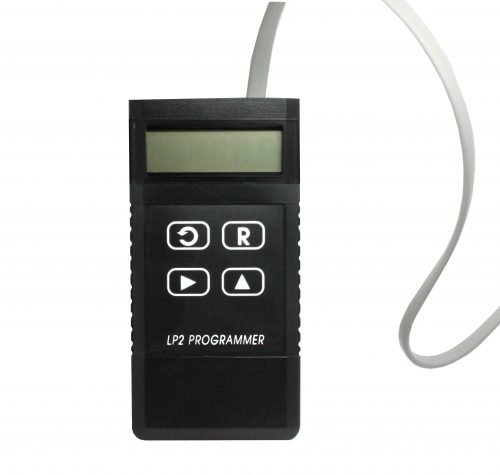
Q. How do I configure the LCI.
A. The LCI is configured using the on board keypad and display. There is a simple single level menu system that is password protected that allow the 5 parameters to be entered.
Q. What is the function of the LED display.
A. When the system is healthy and all load cells are operating within the parameters set the display will show “good”.
If there is an error, the display will show the error codes. These codes relate to the load cell(s) causing the fault and an error number indicating what the fault is e.g. “2Er5”, indicates load cell 2 has an excitation fault.
The display can also show the average mV value for the configured amount of load cells connected or show the individual mV for each load cell. Refer to the LCI manual for operation.
Q. How do I use the LCI to signal a fault up-stream in the system?
A. The LCI has a relay contact that is energised when the system is healthy. If a fault is detected the relay is de-energised and the red LED illuminated. It is this relay contact that can be used to indicate a fault to the up-stream system.
Q. What rating is the LCI relay contact?
A. The relay contact rating is 24V dc @ 500mA or 120V ac @ 500mA
Q. What is the warranty period on an LCI?
A. 3 years
Q. What is the cable diameter for the 6 cable glands fitted to the LCI
A. The cable diameter for the 6 glands is 4.5mm to 7mm
Q. Is this a summing unit?
A. Yes, the unit sums the connected load cells. The number of load cells is selectable on the the display.
Q. Can the LCI be used to monitor over/under load?
A. The max and min mV levels can be set in the range +/- 50 mV and are then applied to each load cell output.
Q. Will the LCI warn if the load cells are out of balance?
A. Yes, the maximum allowed difference between load cell outputs can be set in the +/- 50 mV range.
Q. There are no power connections, why?
A. The LCI uses the excitation voltage that is provided to the load cells.
Q. What are the alarm options?
A. There is an alarm LED on the LCI board that lights up when there is a fault. The display will show the load cell and error type. There is also a relay output to drive an alarm.
For more ‘Frequently Asked Questions’ please see our Knowledge Centre